
Device settings
Every device has its own settings, which are changed from the "Devices" tab of the commissioning interface. This page is a reference of all the settings per device type.
Where to find the device settings
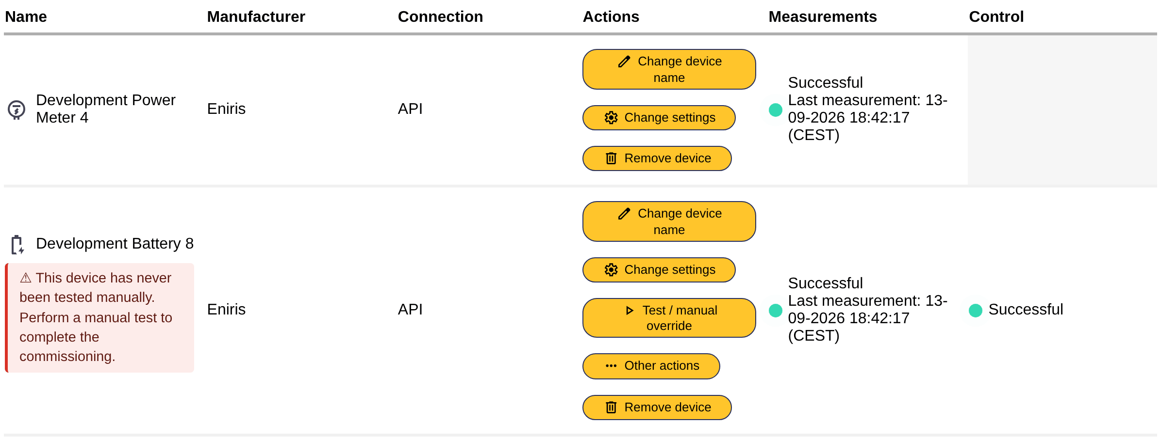
On the "Devices" tab, every known device has a row with its name, manufacturer, connection, measurements and control status. The "Actions" column of a device has a button per action:
- Change device name: rename the device.
- Change settings: the settings described on this page (nominal power, priority, battery capacity, ...). The SmartgridOne Controller shows a warning icon on a device whose settings are not complete yet: check the settings of such a device.
- Change driver inputs: the inputs that were asked when the device was added (for example an IP address, a serial number or an API key), for the devices whose driver allows changing them afterwards. The change is applied to the live device, no restart is needed.
- Test / manual override: send a specific setpoint to the device for a limited time, see Testing and manual override. While a test runs, Stop test / manual override ends it.
- Other actions: device-specific actions that the driver offers, for example resetting an alarm or synchronising the clock of the device. Only shown for devices whose driver supports such actions. Choose the action and click "Execute action"; while the action is executed the interface may seem to hang until the communication channel to the device is free.
- Remove device: deletes the device. Deleted devices are also removed from the external signals they were part of.
Note
The save button of the settings page is at the bottom of the page. When a device is part of a group of devices (for example a hybrid inverter with its battery and PV inputs), the settings of all the devices of the group are shown on one page.
Settings that many devices have
| Setting | Explanation |
|---|---|
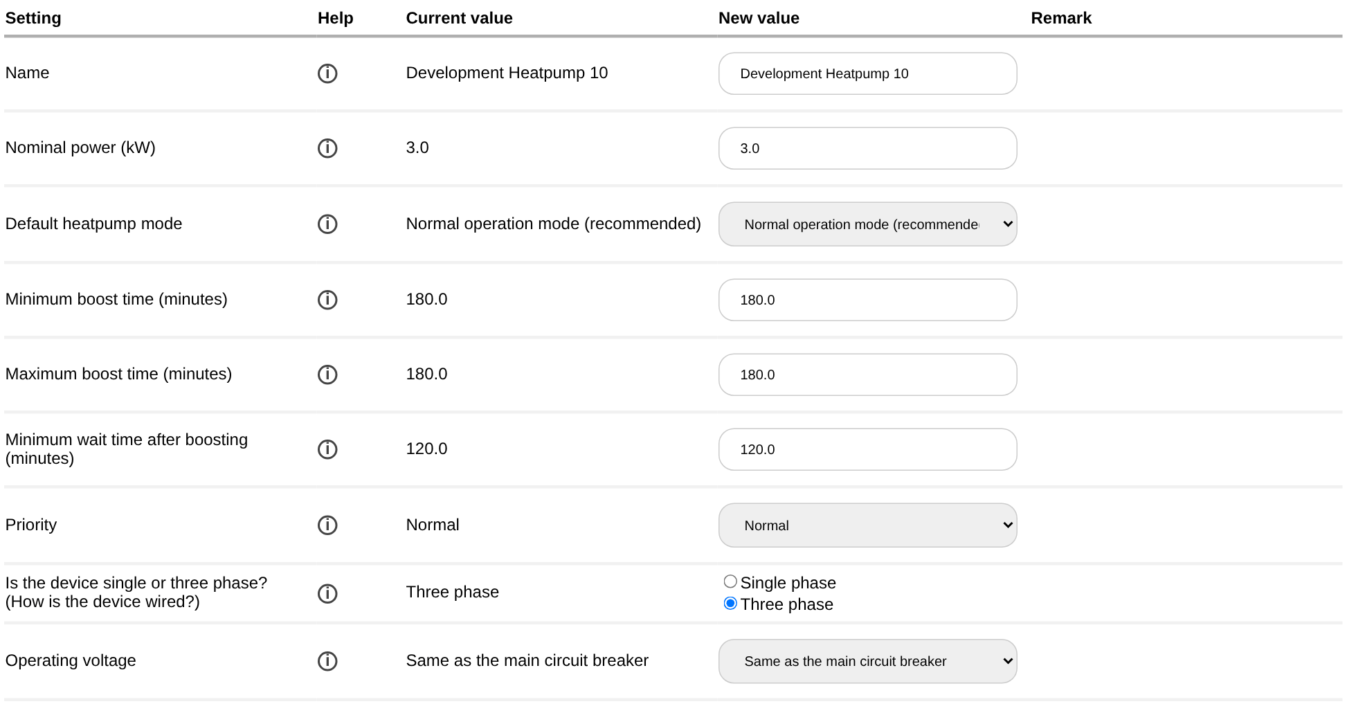
| Name | The name of the device, as shown in the commissioning interface, the app and the portal. |
| Nominal power (kW) | The nominal power of the device. For an inverter this is the AC power it can deliver, for a load the power it draws when it is on. The SmartgridOne Controller uses it to plan the device, so a wrong nominal power leads to wrong control. Batteries, EV chargers, heat pumps, boilers, on/off loads and PV inputs all have it. |
| Priority | Lowest, Low, Normal (default), High or Highest. Indicates whether the device has a higher or lower priority when it is scheduled. Available on batteries, EV chargers, heat pumps, boilers and on/off loads. See Device priorities. |
| Is the device single or three phase? (How is the device wired?) | How the device is physically wired. This is a wiring specification that the SmartgridOne Controller needs for accurate power and current calculations: setting "single phase" for a device that is wired for three phases does not force it to use one phase, but disrupts control and monitoring. |
| Operating voltage | "Same as the main circuit breaker" (default) or "Other". Choose "Other" for a device that operates or measures at another voltage level than the grid connection point, for example a device behind a transformer. With "Other", you also enter the Nominal voltage type (phase-neutral or phase-phase) and the Nominal voltage (V). |
| Is the device connected to the neutral wire? and Device phase L1/L2/L3: which is the corresponding phase of the main energy meter? | Only shown when the retired true three phase working mode is enabled (see Advanced settings). Maps the terminals of the device to the phases of the main energy meter. You must verify this with a multimeter or similar. |
Energy meters
| Setting | Explanation |
|---|---|
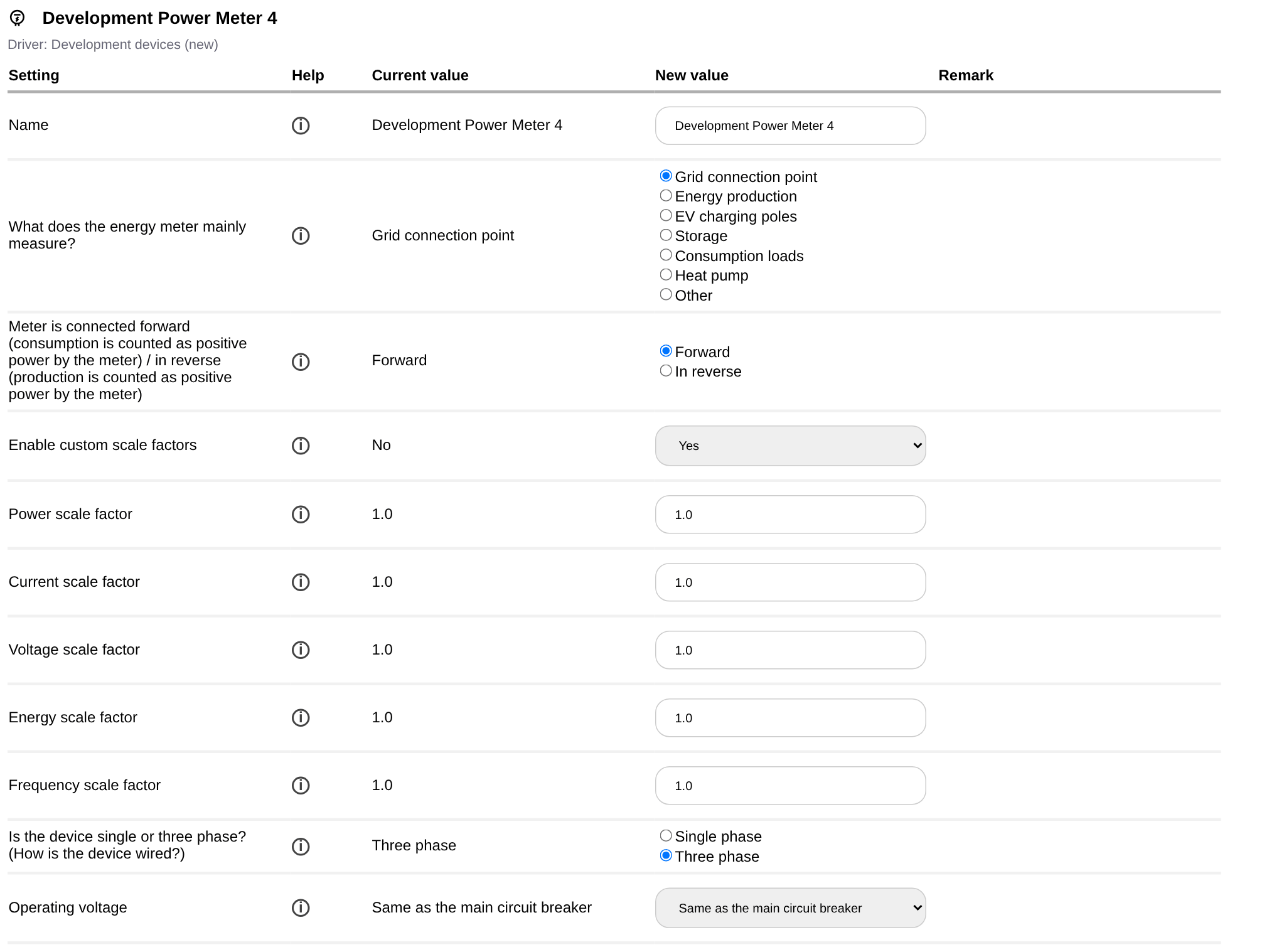
| What does the energy meter mainly measure? | Grid connection point, Energy production, EV charging poles, Storage, Consumption loads, Heat pump or Other. This lets the SmartgridOne Controller categorize the measurements: a meter that measures energy production shows up as PV production in the dashboard and the app. |
| Meter is connected forward / in reverse | Whether consumption is counted as positive power by the meter (forward) or production is counted as positive (in reverse). See Reverse energy meter readings. |
| Enable custom scale factors | Yes or No. With Yes, the power, current, voltage, energy and frequency scale factors appear. The measurements are multiplied by these factors. See Rescale energy meter readings. |
Batteries
| Setting | Default | Explanation |
|---|---|---|
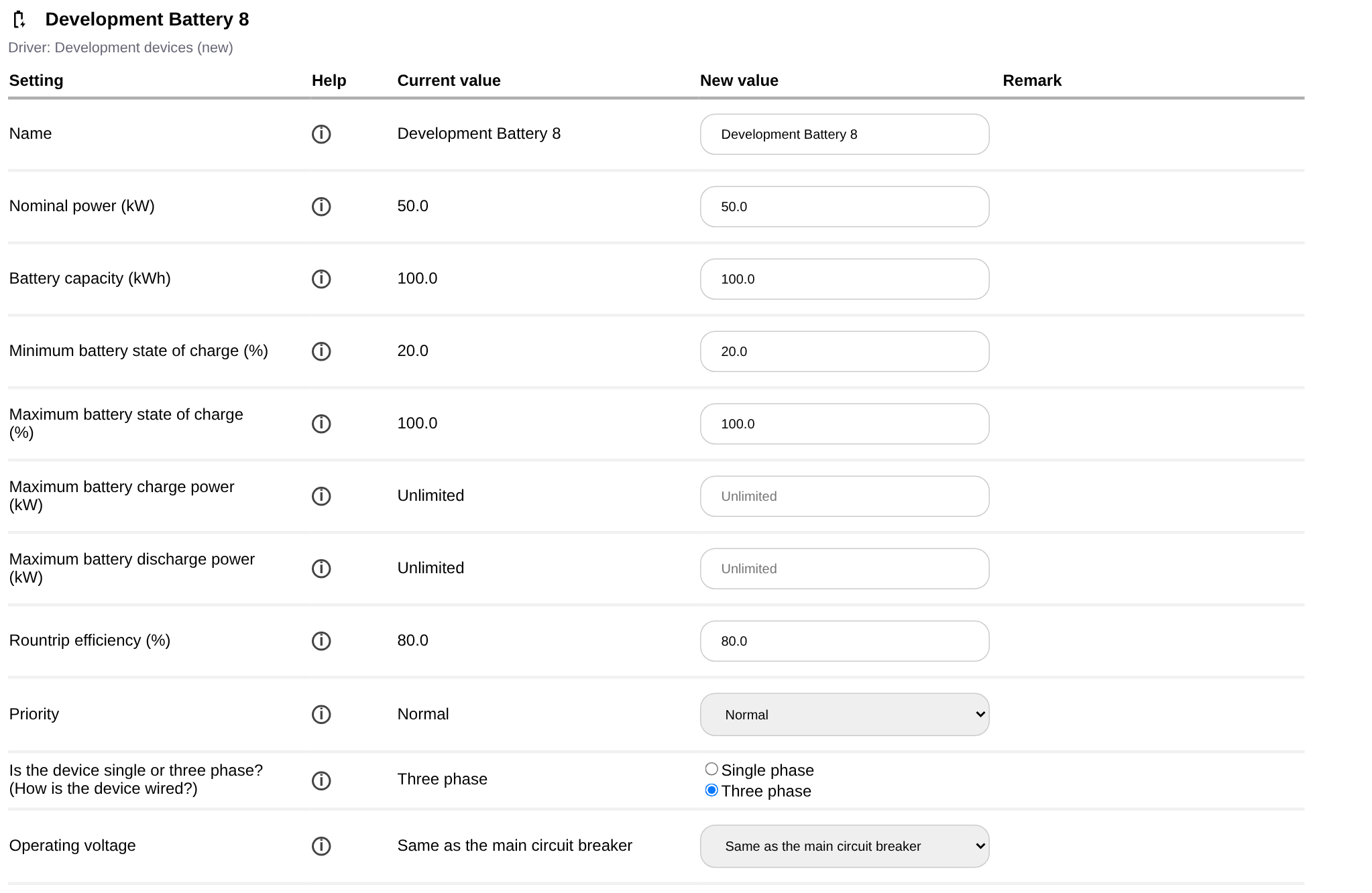
| Nominal power (kW) | read from the device where possible | The power at which the battery can charge and discharge. |
| Battery capacity (kWh) | read from the device where possible | The usable capacity of the battery. |
| Minimum battery state of charge (%) | 20 | The state of charge to which the battery may be discharged. 20% is recommended for lithium-ion batteries, 50% for lead-acid batteries. The SmartgridOne Controller stops discharging 1% above this value and charges the battery a little when it drops below it, see Troubleshooting: control issues. |
| Maximum battery state of charge (%) | 100 | The state of charge to which the battery may be charged. |
| Maximum battery charge power (kW) | Unlimited | Caps the charge power. Left empty, the charge power is at most the nominal power. |
| Maximum battery discharge power (kW) | Unlimited | Caps the discharge power. Left empty, the discharge power is at most the nominal power. |
| Roundtrip efficiency (%) | 80 | The roundtrip efficiency of the battery. Together with the wear cost, this determines the cost of using the battery in cost optimization. See Accounting for the battery wear and efficiency. |
| Priority | Normal | See above. |
Hybrid inverters and PV
- A hybrid inverter has a nominal power (kW). Its battery and its PV inputs are separate devices with their own settings.
- A solar inverter, PV input or solar optimizer has a nominal power (kW) and the question "Are there PV panels connected to this input?". Answer "No" for the inputs of an inverter that are not used, so that they are not counted as production.
- A solar plant or solar installation (a group of inverters) has a nominal power (kW).
EV chargers and connectors
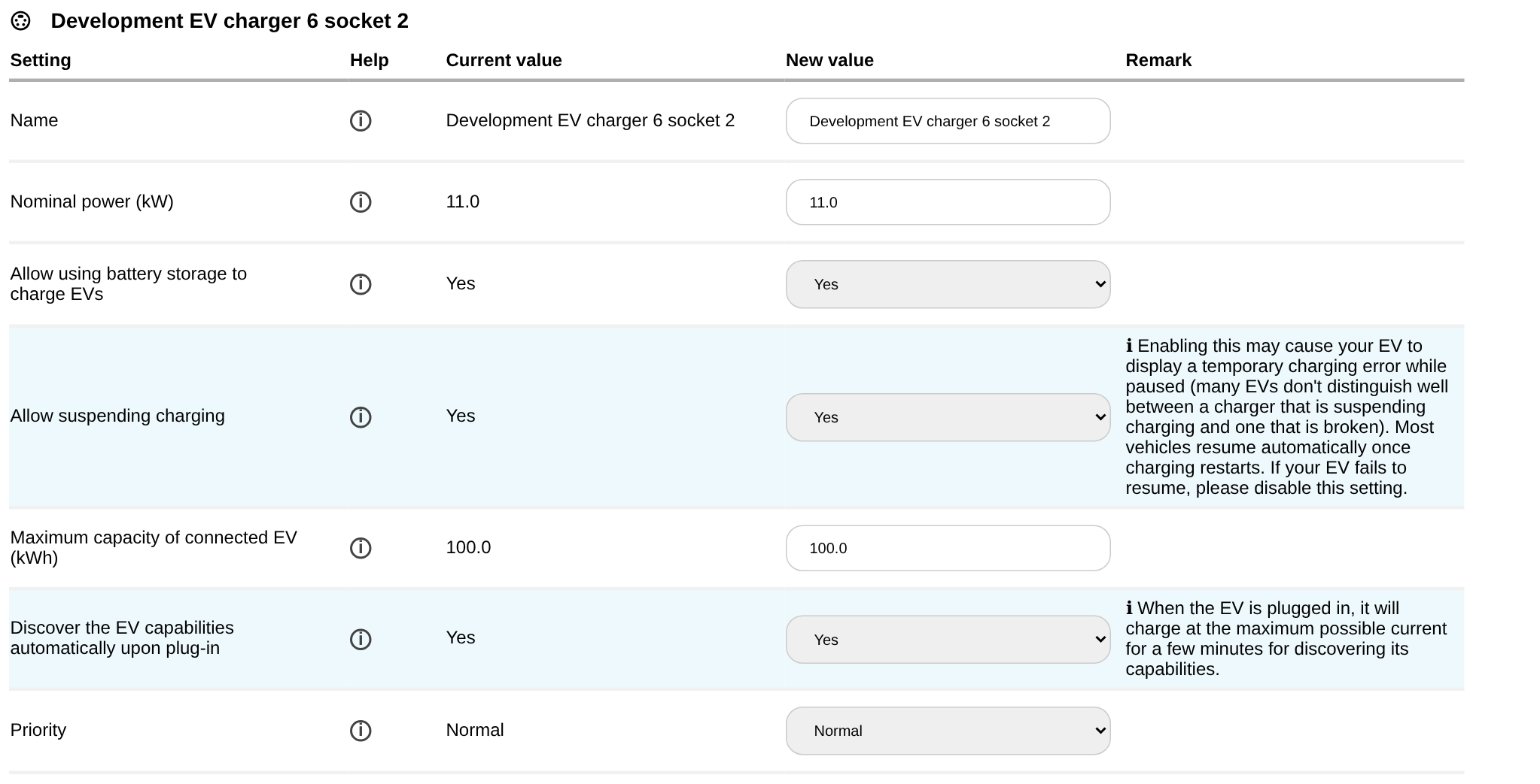
An EV charger has one or more connectors (sockets). The charger itself has a nominal power and the setting "Allow suspending charging"; every connector has its own settings.
| Setting | Default | Explanation |
|---|---|---|
| Nominal power (kW) | read from the device where possible | The maximum charge power of the charger or the connector. |
| Allow suspending charging | Yes | With Yes, charging may be fully paused to wait for the most cost-effective or green energy windows. Some EVs do not support a full suspension and need a constant minimum current: if your car shows an error or fails to start charging, set this to No. |
| Allow using battery storage to charge EVs | Yes | Whether battery storage may be used to charge EVs on this connector. Only applied when the storage is in self-consumption or cost optimization; when the storage is in peak shaving or follows a setpoint, it is always used if needed. See Energy storage and EVs. |
| Maximum capacity of connected EV (kWh) | 100 | The battery capacity of the largest EV that charges on this connector, used for the planning. |
| Discover the EV capabilities automatically upon plug-in | Yes | When an EV is plugged in, the SmartgridOne Controller gives it the maximum allowed current for a few moments to discover how much current it draws and how many phases it uses. This is required for a good planning. Leave it on if different EVs charge on this connector. |
| Maximum current the EV can draw (A) | 32 | The maximum current per phase of the EV. Only shown and used when the automatic discovery is disabled. |
| Number of phases the EV can use | Three phases | Three phases, two phases or single phase. Only shown and used when the automatic discovery is disabled. |
| Enable Smart Phase Switching (Experimental) | No | Lets the charger switch between one and three phases to charge on lower solar output without importing from the grid. Only shown for chargers that support phase switching. Not all cars support this: disable it if your car goes into fault. |
| Priority | Normal | See above. |
Heat pumps
| Setting | Default | Explanation |
|---|---|---|
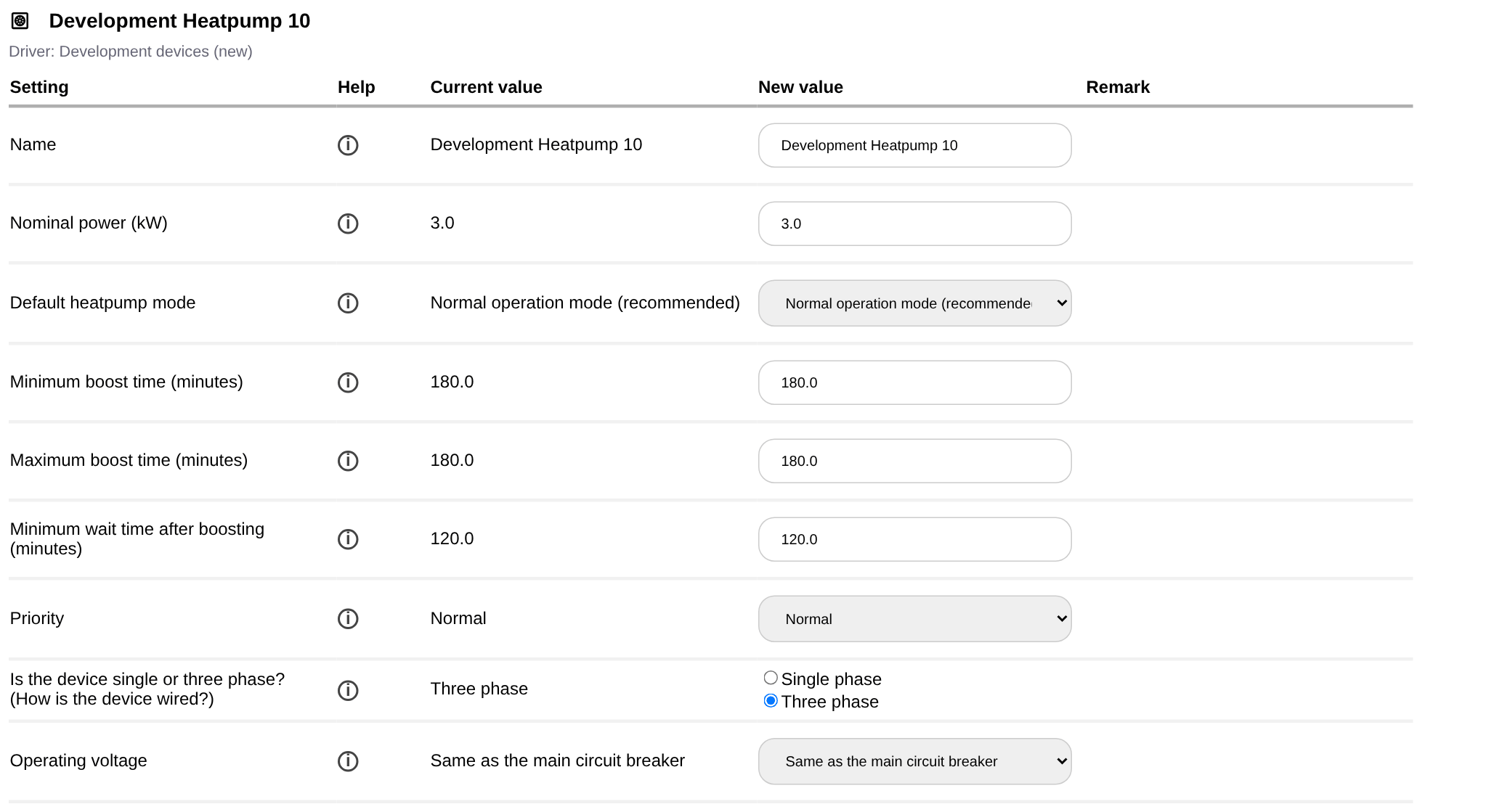
| Nominal power (kW) | The electrical power of the heat pump. | |
| Default heatpump mode | Normal operation mode | In Normal operation mode the heat pump works on its own and is only boosted or blocked when that is beneficial. In Blocking mode it is blocked by default and only released when beneficial; in Boosting mode it is boosted by default and only released when beneficial. A mode that the heat pump does not support falls back to normal operation. Caution: the SmartgridOne Controller is not a thermostat, so the blocking and boosting modes can influence the comfort significantly. |
| Minimum and maximum time in normal operation mode (minutes) | 180 | How long the heat pump stays at least and at most in normal operation when it is not optimal to block or boost it. |
| Minimum and maximum block time (minutes) | 180 | How long the heat pump is at least and at most blocked when it is optimal to block it. |
| Minimum wait time after blocking (minutes) | 120 | How long the heat pump stays in normal operation after it was blocked, so that the temperature of the building does not drop too much. |
| Minimum and maximum boost time (minutes) | 180 | How long the heat pump is at least and at most boosted when it is optimal to boost it. |
| Minimum wait time after boosting (minutes) | 120 | How long the heat pump stays in normal operation after it was boosted. |
| Priority | Normal | See above. |
The block times are only shown for heat pumps that can be blocked, and the boost times only for heat pumps that can be boosted.
See Heat pumps, boilers and on/off devices for what blocking and boosting mean.
Boilers
A boiler and a controllable boiler (a boiler whose power can be modulated) have a nominal power (kW) and a priority.
Relays, switches and other on/off loads
| Setting | Default | Explanation |
|---|---|---|
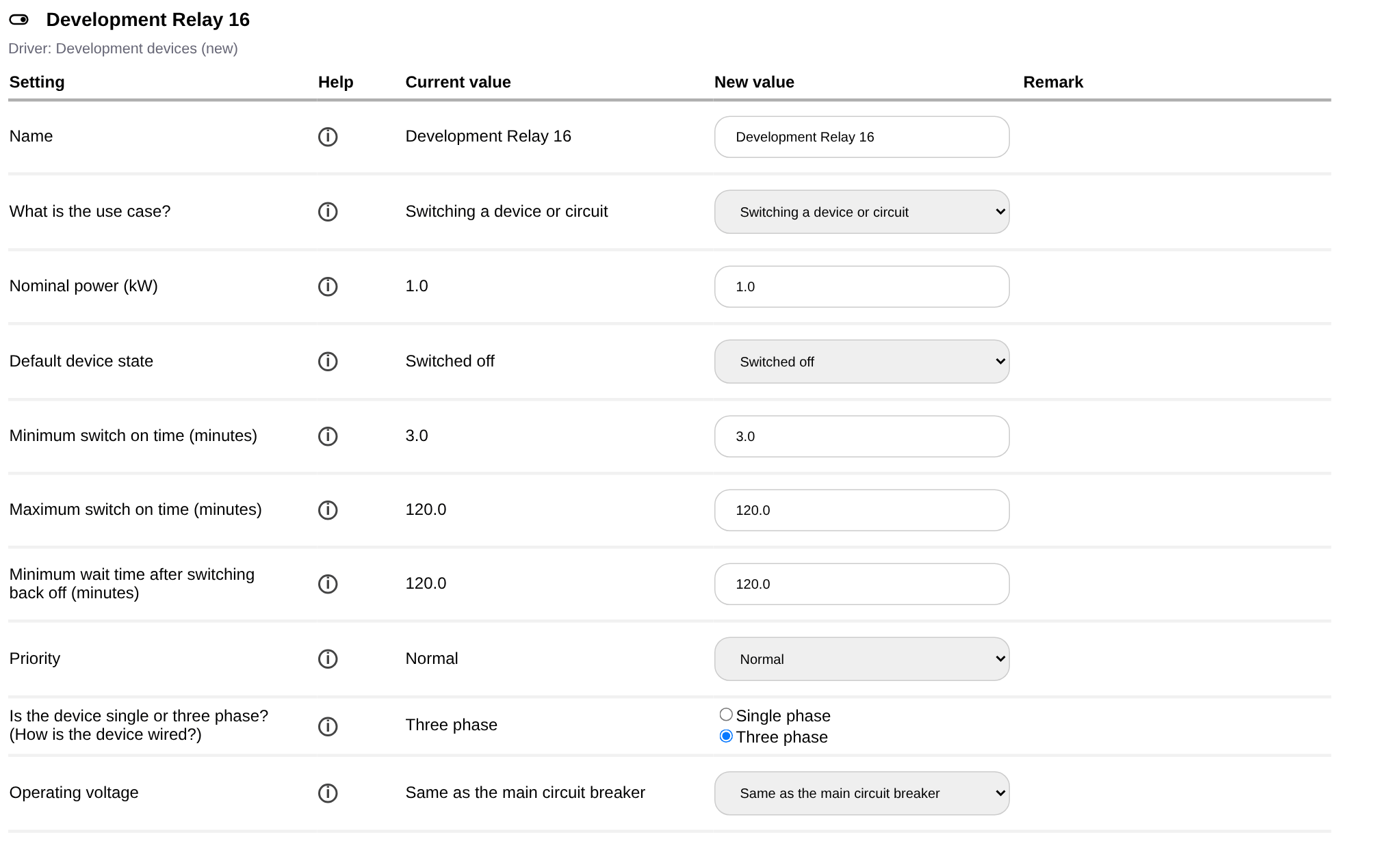
| What is the use case? | Switching a device or circuit: the relay switches a load that the SmartgridOne Controller plans like any other on/off load. Direct passthrough of an external control signal: the relay follows an external signal directly, without the local control modes, limits or timing constraints. See Direct relay or switch control. | |
| Nominal power (kW) | 100 | The power of the load behind the relay. |
| Default device state | Switched on: the device is on by default and is only switched off when it is optimal to block its consumption or when an external signal says so (for example a fridge that may be off for an hour, or a boiler that may be off for 8 hours). Switched off: the device is off by default and is only switched on when it is optimal to boost consumption or when an external signal says so (for example pool heating). Caution: do not use "Switched off" for devices whose comfort you care about, because they can stay off for extended periods. In passthrough mode this is the fallback state when no external signal is present. | |
| Minimum and maximum switch off time (minutes) | 3 and 120 | How long the device is at least and at most switched off when it is optimal to reduce consumption. |
| Minimum wait time after switching back on (minutes) | 120 | How long the device stays on after it was switched back on, for example to make sure a boiler heats some water. |
| Minimum and maximum switch on time (minutes) | 3 and 120 | How long the device is at least and at most switched on when it is optimal to increase consumption. |
| Minimum wait time after switching back off (minutes) | 120 | How long the device stays off after it was switched back off. |
| Priority | Normal | See above. |
Only the timings that apply to the selected default device state are shown: the switch on times for a relay that is switched off by default, and the switch off times for a relay that is switched on by default.
Note
The timing settings are ignored when the relay is directly controlled by an external signal or by the peak shaving relay cascade. They are also ignored when the grid limits are exceeded.
Groups (switchboards)
A group created on the Groups tab has two settings:
| Setting | Default | Explanation |
|---|---|---|
| Circuit breaker current (A) | Unlimited | The current limit of the circuit breaker of the switchboard. The SmartgridOne Controller keeps the current of the devices in the group below it. |
| Protected phases | L1, L2, L3 and N | The phases that the circuit breaker protects, for example "L1 and N" for a single phase sub-board. |