Carlo Gavazzi VMU-S String Measurement Unit
Supported Devices
| Device Type | Modbus TCP (Ethernet) | RS485 |
|---|---|---|
| Carlo Gavazzi VMU-S | ❌ | ✅ |
Note
System Architecture The VMU-S is a modular system. It requires a VMU-M (Master) unit to handle the RS485 communication. The VMU-S modules plug directly into the side of this master unit.
| VMU-S (String Unit) | VMU-M (Master Unit) |
|---|---|
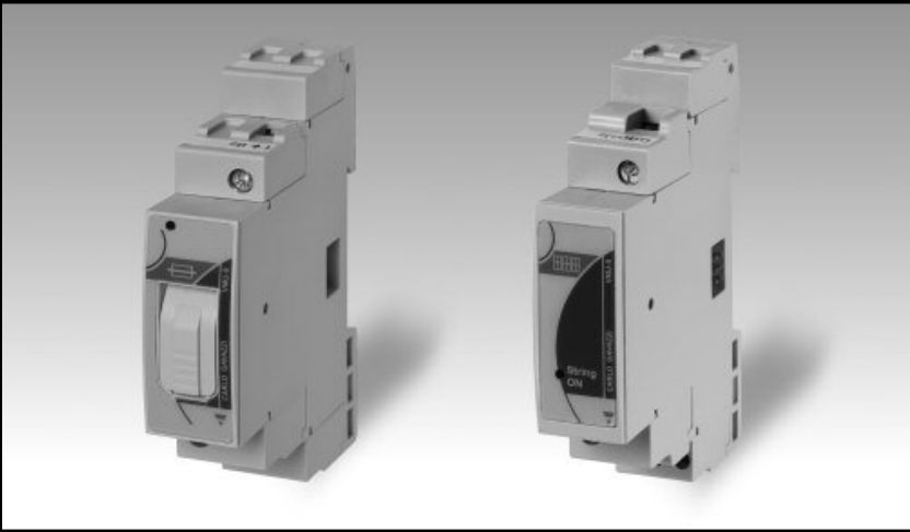 | 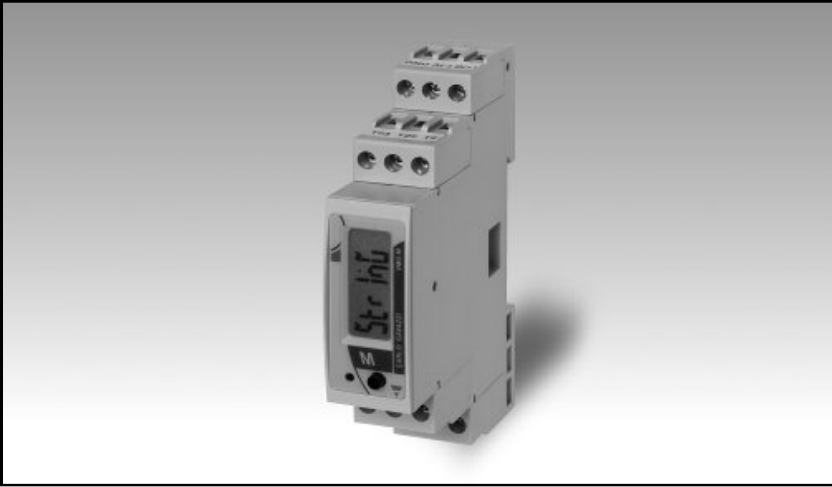 |
Wiring
Bus Connection (Mechanical)
The VMU-S connects to the VMU-M master unit via the local bus connector on the side.
Caution
Do not Hot-Swap! Risk of equipment damage: Only join or separate the VMU-S modules from the Master unit when the power supply is OFF. Connecting modules while the system is powered can damage the internal electronics.
RS485 (Data Connection)
Although you are measuring with the VMU-S, the RS485 cable connects to the VMU-M Master unit. The VMU-S sends its data internally to this master unit.
RS485 Wiring
- For correct RS485 wiring: Follow the guidelines for RS485 wiring.
- If the wiring shown in the table below is incorrect, please let us know.
- There is no general consensus in the industry about the usage of A and B for the RS485 polarity, so it may be counterintuitive and opposite of what you might expect for some devices.
| Device | SmartgridOne Controller model OM1 | SmartgridOne Controller model IG8 | RS485-USB converter | RS485-Ethernet converter |
|---|---|---|---|---|
| Terminal 11 / B- | RS485 A | RS485_POS | RS485 A | TX+ |
| Terminal 12 / A+ | RS485 B | RS485_NEG | RS485 B | TX- |
| Terminal 10 / GND | RS GND | GND | Not available | G |
DC Power Wiring (VMU-S)
The VMU-S modules are wired in series with the PV strings:
- Top Terminals (1 & 3): Input from PV String (+ and -).
- Bottom Terminals: Output to Inverter (+ and -).
Warning
Polarity Ensure the correct polarity (Top to Bottom). If the polarity is reversed, the Status LED on the VMU-S will blink Violet (Blue -> Violet cycle).
Configuration
1. Hardware Configuration (VMU-M)
Since the VMU-S has no display, you configure the Modbus settings on the Master unit (VMU-M).
NOTE: RS485 Device Addresses
- You MUST give each device on the RS485 bus a unique address. Check the manual of the device on how to do this.
- Use lower addresses first (1, 2, ...) because the SmartgridOne Controller will find them faster!
- For each device, it is generally recommended to stick with the factory default baud rate, parity, and stop bits. The SmartgridOne Controller will scan on those first.
- On the VMU-M unit, hold the joystick to enter the menu (Password: 0000).
- Go to SETTINGS > COM.
- Set ADDRESS (e.g., 1). This is the address you will use in the Controller.
- Set BAUDRATE to 9600 (default).
- Set PARITY to No (default).
2. Module Scan
After installing the VMU-S modules, the Master unit must recognize them:
- On the VMU-M, go to SETTINGS > SYSTEM.
- Select Modules Scan.
- Verify on the display that the number of found modules matches the amount of installed VMU-S units.
3. Controller Configuration
When adding this device to the Controller, you will be asked for the Amount of Strings.
- Enter the total number of VMU-S modules connected to this specific VMU-M Master unit.
- The driver will automatically scan and add each string as a sub-device.
