

Kehua
Supported Devices
| Device Type | Modbus TCP (Ethernet) | RS485 |
|---|---|---|
| BCS1725K-B-HUD | ✅ | ✅ |
| NXPCS | ||
| BCS200K-B-HM | ||
| SPI three-phase string PV series (SPI8000/12K/23K/33K-B X2, SPI125K-B, SPI250K/320K-B-H) | ❌ |
Wiring
For correct ethernet wiring: Follow the the guidelines for ethernet wiring.
RS485
PCS models (BCS1725K-B-HUD, NXPCS, BCS200K-B-HM)
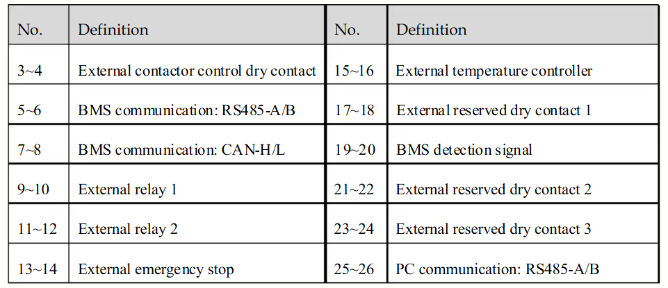
To establish communication between the PCS and Controller, use the RS485 interface available on the external wiring terminal bar, as shown below. This terminal provides dedicated ports for RS485 communication, which is used for both PC and BMS connections.

RS485 Wiring
- For correct RS485 wiring: Follow the guidelines for RS485 wiring.
- If the wiring shown in the table below is incorrect, please let us know.
- There is no general consensus in the industry about the usage of A and B for the RS485 polarity, so it may be counterintuitive and opposite of what you might expect for some devices.
| Device | SmartgridOne Controller model OM1 | SmartgridOne Controller model IG8 | RS485-USB converter | RS485-Ethernet converter |
|---|---|---|---|---|
| RS485 A (Pin 5) | RS485 A | RS485_POS | RS485 A | TX+ |
| RS485 B (Pin 6) | RS485 B | RS485_NEG | RS485 B | TX- |
| N/A | RS GND | GND | Not available | G |
SPI string PV inverters
The SPI string PV inverters use a different physical RS485 connection than the PCS models above. The serial settings are the same for all SPI models:
| Setting | Value |
|---|---|
| Protocol | Modbus RTU |
| Baud rate | 9600 (default), configurable to 2400 / 4800 / 19200 / 38400 / 115200 |
| Parity | None |
| Data bits | 8 |
| Stop bits | 1 |
| Modbus address | 1 - 247 |
SPI-B X2 series (SPI8000-B-X2 up to SPI33K-B X2)
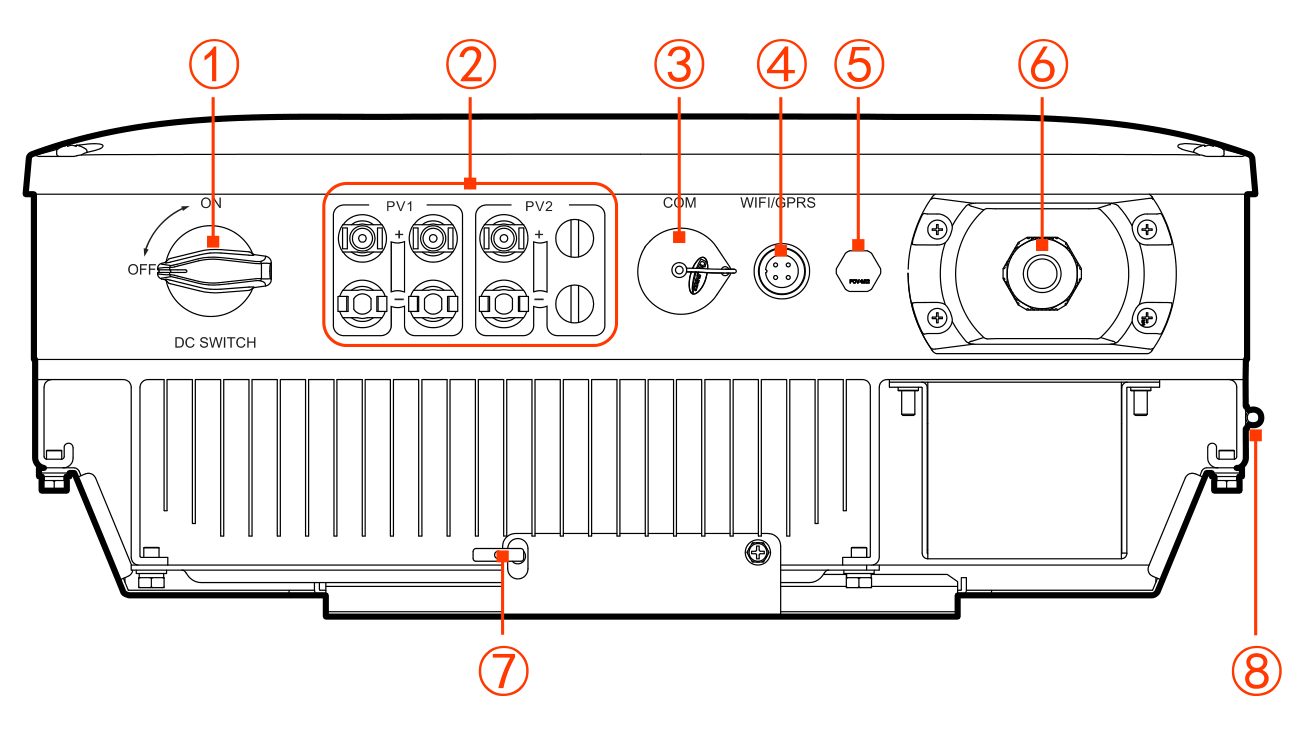
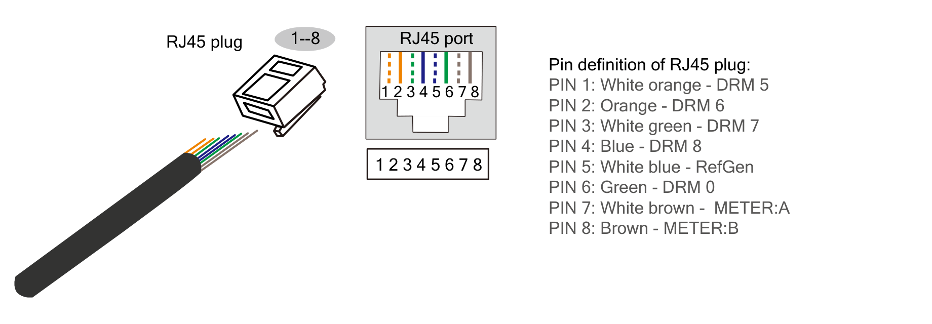
The COM. port (a waterproof RJ45 plug, ③ in the figure below) is the only wired RS485 interface on these models. It must be configured as RS485 communication port (not as DRM port). Pins 7 and 8 of the RJ45 plug are the RS485 A and B lines.
RS485 Wiring
- For correct RS485 wiring: Follow the guidelines for RS485 wiring.
- If the wiring shown in the table below is incorrect, please let us know.
- There is no general consensus in the industry about the usage of A and B for the RS485 polarity, so it may be counterintuitive and opposite of what you might expect for some devices.
| Device | SmartgridOne Controller model OM1 | SmartgridOne Controller model IG8 | RS485-USB converter | RS485-Ethernet converter |
|---|---|---|---|---|
| RS485 A (RJ45 pin 7, white-brown) | RS485 A | RS485_POS | RS485 A | TX+ |
| RS485 B (RJ45 pin 8, brown) | RS485 B | RS485_NEG | RS485 B | TX- |
| N/A | RS GND | GND | Not available | G |
Important — verify on site: the Kehua user manuals label pins 7 and 8 as METER:A / METER:B and only describe them for the smart-meter (zero-export) function. Kehua's northbound Modbus protocol (V2.11) does list these models as supporting RS485 monitoring, and this RJ45 is the only wired RS485 interface they have, but Kehua's documentation does not explicitly confirm that monitoring uses these pins. Verify this connection on site or with Kehua support before relying on it. Also note that if the zero-export smart-meter function is in use, this port is occupied by the meter and cannot be used for monitoring at the same time.
The Modbus address and baud rate of these models are set with the Kehua monitoring software (default baud rate 9600). Multiple inverters can be daisy-chained on the same RS485 bus.
Larger SPI models (SPI125K-B, SPI250K-B-H, SPI320K-B-H)
These models have a dedicated RS485 port on the communication board inside the wiring box; the Kehua user manual confirms this port "is mainly used for LAN monitoring, which can realize the background remote monitoring". Connect the RS485 wires to that port and route them separately from the AC and DC power wiring to avoid communication interference.
RS485 Wiring
- For correct RS485 wiring: Follow the guidelines for RS485 wiring.
- If the wiring shown in the table below is incorrect, please let us know.
- There is no general consensus in the industry about the usage of A and B for the RS485 polarity, so it may be counterintuitive and opposite of what you might expect for some devices.
| Device | SmartgridOne Controller model OM1 | SmartgridOne Controller model IG8 | RS485-USB converter | RS485-Ethernet converter |
|---|---|---|---|---|
| RS485 A | RS485 A | RS485_POS | RS485 A | TX+ |
| RS485 B | RS485 B | RS485_NEG | RS485 B | TX- |
| N/A | RS GND | GND | Not available | G |
- On the SPI 75K-150K models (e.g. SPI125K-B), the Modbus address is set in binary with the SW1 dial switch on the communication board (e.g.
000001= address 1). The baud rate is set with the Kehua WiseEnergy software (default 9600). - On the SPI-B-H models (SPI250K-B-H, SPI320K-B-H), the RS485 connection is located in the COM. wiring box, next to the (optional) Ethernet connection.