Supported Devices
| Device Type | Modbus TCP (Ethernet) | RS485 | Curtailment |
|---|---|---|---|
| Inverx Elite XLiT5 | ❌ | ✅ | ✅ |
| Inverx Elite XLiT6 | |||
| Inverx Elite XLiT8 | |||
| Inverx Elite XLiT10 |
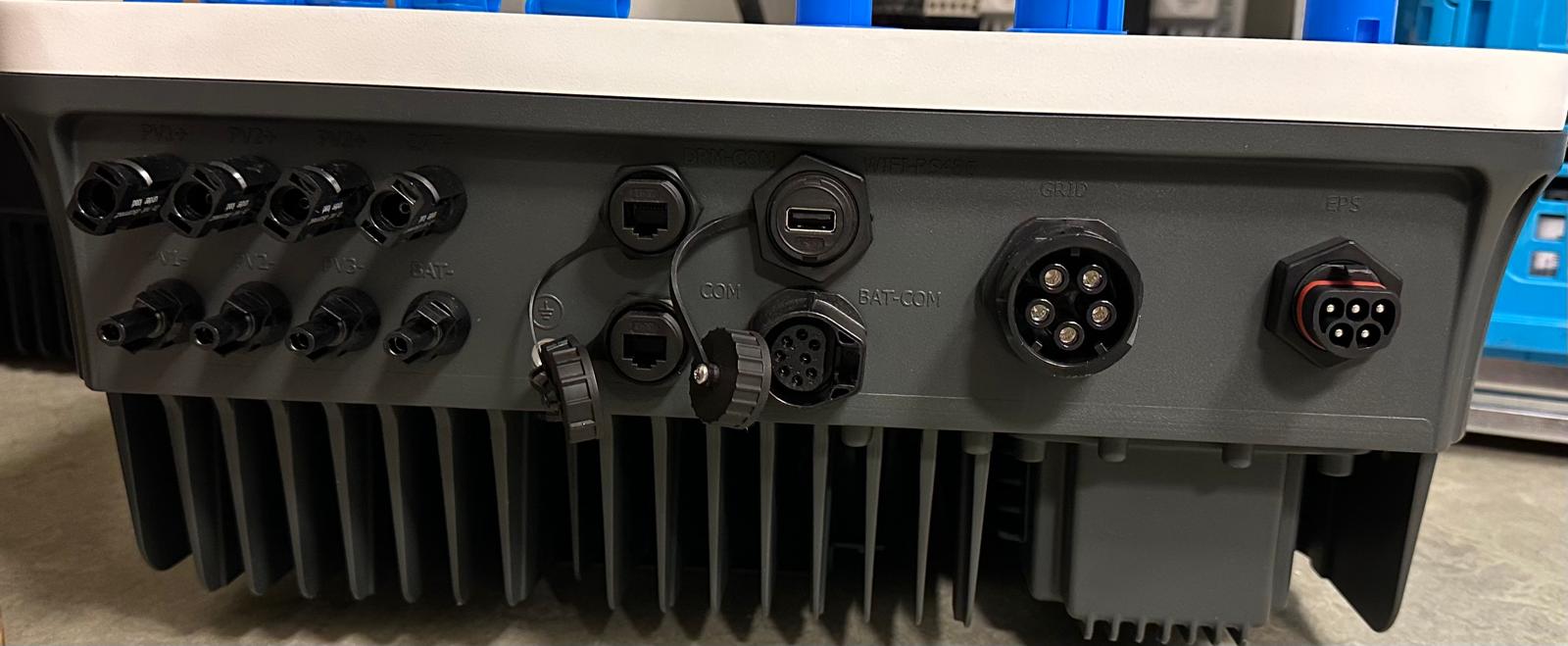
Wiring
Connect the RS485 lines to the ARM_485 terminal block on the inverter:
- ARM_485_A → D+ (positive / non-inverting)
- ARM_485_B → D– (negative / inverting)
RS485 Wiring
- For correct RS485 wiring: Follow the guidelines for RS485 wiring.
- If the wiring shown in the table below is incorrect, please let us know.
- There is no general consensus in the industry about the usage of A and B for the RS485 polarity, so it may be counterintuitive and opposite of what you might expect for some devices.
| Device | SmartgridOne Controller model OM1 | SmartgridOne Controller model IG8 | RS485-USB converter | RS485-Ethernet converter |
|---|---|---|---|---|
| ARM_485_A (D+) | RS485 A | RS485_POS | RS485 A | TX+ |
| ARM_485_B (D–) | RS485 B | RS485_NEG | RS485 B | TX- |
| GND | RS GND | GND | Not available | G |
NOTE: RS485 Device Addresses
- You MUST give each device on the RS485 bus a unique address. Check the manual of the device on how to do this.
- Use lower addresses first (1, 2, ...) because the SmartgridOne Controller will find them faster!
- For each device, it is generally recommended to stick with the factory default baud rate, parity, and stop bits. The SmartgridOne Controller will scan on those first.
Configuration
1. Check RS485 settings on the inverter
The factory default RS485 communication parameters are:
| Parameter | Value |
|---|---|
| Protocol | Modbus RTU |
| Baud rate | 9600 |
| Data bits | 8 |
| Parity | None |
| Stop bits | 1 |
| Address range | 1 – 247 |
The default slave address is 1. The address can be changed in the inverter menu if multiple devices share the same RS485 bus.
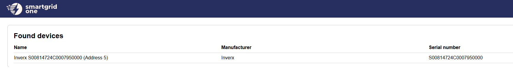
2. Add the device in the SmartgridOne Controller
- Open the SmartgridOne Controller commissioning interface.
- Go to Devices → Add device.
- Select the connection type RS485.
- Choose Fairland Inverx Hybrid Inverter RTU from the device list.
- The controller will automatically scan for the device using the default settings (9600 baud, 8N1).
- If the device is not found automatically, set the Modbus address manually.
- (Optional) Set the number of PV strings (MPPT inputs) connected — enter a value between 1 and 4. Leave blank to use the default (4).
- (Optional) Set the number of battery packs installed — enter a value between 1 and 32. Leave blank to use the default (1).
- Save and apply the configuration.
Note
Setting the correct PV string count prevents the controller from polling unused MPPT inputs. If fewer strings are physically connected than the default of 4, the controller verifies each string by reading its voltage on first connection.
3. Verify communication
After saving, check that live data appears for:
- Grid: active power (import/export in W), phase voltages (L1/L2/L3), frequency
- PV: power per MPPT string and total PV power
- Battery: voltage, current, state of charge (SOC), state of health (SOH), power
Note
If no battery is physically installed, the controller will display a "No battery detected by inverter" warning. This is expected behaviour — the inverter reports battery type code 100 (no battery) and the controller suppresses battery metrics accordingly.
SmartgridOne / Curtailment Control
The Fairland Inverx Elite supports two control modes:
| Control mode | Type | Description |
|---|---|---|
| AC export limit | limit | Limits grid feed-in power as a percentage of rated inverter power. Supports soft limit (default) and hard limit modes. |
| Battery setpoint | setpoint | Forces the battery to charge or discharge at a specific power level (W). |
AC export limit details
- The export limit percentage is calculated from a live reading of the inverter's rated power (register 4051).
- Soft limit: holding register
21221is set to161. - Hard limit: holding register
21221is set to162. - Disabled: holding register
21221is set to85(SmartGrid mode off).
Battery setpoint details
- Power is written in 10 W steps (raw value = W ÷ 10, clamped to 0 – 600,000 mW).
- Charge: command register
23147=0xAA(170) + power register23148= raw value. - Discharge: command register
23147=0xBB(187) + power register23148= raw value. - Stop forced mode: command register
23147=0xCC(204), energy management mode register23146=0. - Forced charge/discharge mode is activated by writing
2to register23146.
Known Issues
Warning
Battery type always returns code 1080. The inverter consistently reports battery type 1080, which is not documented in the official Modbus protocol. This is a known hardware/firmware bug and does not affect operation — the controller uses voltage and SOC values to confirm battery presence instead.
Note
Per-string PV power is calculated, not measured. There is no dedicated power register per MPPT string. Power is derived as voltage × current for each string.