Esta página describe la comunicación con un inversor híbrido serie LD de Autarco mediante Modbus-RTU (rs485).
Por defecto, el inversor está configurado en la dirección 1. La interfaz RS485 es un conector de 4 pines en la parte inferior del inversor
detrás de una placa protectora. La posición exacta está marcada en el recuadro naranja en la imagen de abajo:
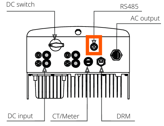
Observando más de cerca, el puerto se ve así:

Se debe usar un conector adecuado para este conector de 4 pines en el inversor Autarco para conectar al SmartgridOne Controller. En el SmartgridOne Controller, el inversor puede conectarse al puerto RS485. El cableado es el siguiente:
Info
RS485 Wiring
- For correct RS485 wiring: Follow the guidelines for RS485 wiring.
- If the wiring shown in the table below is incorrect, please let us know.
- There is no general consensus in the industry about the usage of A and B for the RS485 polarity, so it may be counterintuitive and opposite of what you might expect for some devices.
| Device | SmartgridOne Controller model OM1 | SmartgridOne Controller model IG8 | RS485-USB converter | RS485-Ethernet converter |
|---|---|---|---|---|
| Pin 3 | RS485 A | RS485_POS | RS485 A | TX+ |
| Pin 4 | RS485 B | RS485_NEG | RS485 B | TX- |
| N/A | RS GND | GND | Not available | G |
Advertencia
NOTE: RS485 Device Addresses
- You MUST give each device on the RS485 bus a unique address. Check the manual of the device on how to do this.
- Use lower addresses first (1, 2, ...) because the SmartgridOne Controller will find them faster!
- For each device, it is generally recommended to stick with the factory default baud rate, parity, and stop bits. The SmartgridOne Controller will scan on those first.
Last updated February 18, 2026Edit this page