Supported Devices
| Device Type | Modbus TCP (Ethernet) | RS485 |
|---|---|---|
| PLA33 | ✅ | ✅ |
| PLA33RX |
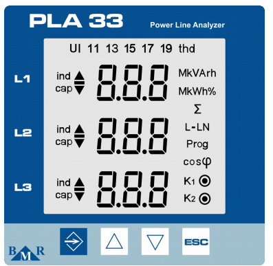
Figure 1: Front panel of the PLA33 showing buttons like SET, cursor keys, and ESC.

Figure 2: Front panel of the PLA33RX showing buttons like ESC, cursor keys, and status LEDs for recording and relay outputs.
Wiring
RS485
For RS485 wiring, follow the guidelines for RS485 wiring.
RS485 Wiring
- For correct RS485 wiring: Follow the guidelines for RS485 wiring.
- If the wiring shown in the table below is incorrect, please let us know.
- There is no general consensus in the industry about the usage of A and B for the RS485 polarity, so it may be counterintuitive and opposite of what you might expect for some devices.
| Device | SmartgridOne Controller model OM1 | SmartgridOne Controller model IG8 | RS485-USB converter | RS485-Ethernet converter |
|---|---|---|---|---|
| A | RS485 A | RS485_POS | RS485 A | TX+ |
| B | RS485 B | RS485_NEG | RS485 B | TX- |
| GND | RS GND | GND | Not available | G |
NOTE: RS485 Device Addresses
- You MUST give each device on the RS485 bus a unique address. Check the manual of the device on how to do this.
- Use lower addresses first (1, 2, ...) because the SmartgridOne Controller will find them faster!
- For each device, it is generally recommended to stick with the factory default baud rate, parity, and stop bits. The SmartgridOne Controller will scan on those first.
Ethernet
For Ethernet wiring, follow the guidelines for Ethernet wiring.
Configuration
RS485 Configuration
To configure RS485 communication on BMR energy meters, follow these steps:
-
Set the Modbus Address:
- Access the settings menu by pressing the SET button for 5 seconds.
- Navigate to the communication menu (
P_2) using the cursor keys. - Set the Id (unique Modbus address) between 1 and 247.
-
Set the Baud Rate:
- In the communication menu (
P_2), configure the bd (baud rate) to match your system. Supported baud rates include9.6 / 19.2 / 38.4 / 57.6 / 115 kBd.
- In the communication menu (
-
Parity and Stop Bits:
- Configure PAr (parity) as
None,Odd, orEven. - Set the St (stop bits) to
1or2as needed.
- Configure PAr (parity) as
-
RS485 Termination:
- If the meter is the last device on the RS485 bus, add a 120 Ω termination resistor.
NOTE: RS485 Device Addresses
- You MUST give each device on the RS485 bus a unique address. Check the manual of the device on how to do this.
- Use lower addresses first (1, 2, ...) because the SmartgridOne Controller will find them faster!
- For each device, it is generally recommended to stick with the factory default baud rate, parity, and stop bits. The SmartgridOne Controller will scan on those first.
Ethernet Configuration (PLA33RX Only)
For devices with Ethernet capability:
- Ensure the Ethernet cable is properly connected.
- Use the Power Monitoring Software (PMS) to configure the IP address, subnet mask, and gateway.
- Verify that the Modbus TCP port is set to 502.