Supported Devices
The PM 5000 series covers a wide range of meters. Capabilities vary by specific model number (e.g., PM51xx are generally RS485 only, while PM5320/PM5340 include Ethernet).
| Device Type | Modbus TCP (Ethernet) | RS485 |
|---|---|---|
| Schneider-Electric PM 5100 / 5110 / 5111 | ❌ | ✅ |
| Schneider-Electric PM 5310 / 5330 / 5331 | ||
| Schneider-Electric PM 5320 / 5340 / 5341 | ✅ |
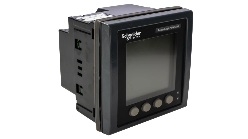
pm5300
Wiring
Ethernet
Applicable only to PM5320, PM5340, and PM5341. For correct ethernet wiring: Follow the guidelines for ethernet wiring.
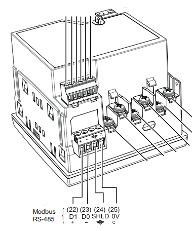
RS485
The RS485 terminals are located on the bottom of the device (connector 6 in the diagram below).
RS485 Wiring
- For correct RS485 wiring: Follow the guidelines for RS485 wiring.
- If the wiring shown in the table below is incorrect, please let us know.
- There is no general consensus in the industry about the usage of A and B for the RS485 polarity, so it may be counterintuitive and opposite of what you might expect for some devices.
| Device | SmartgridOne Controller model OM1 | SmartgridOne Controller model IG8 | RS485-USB converter | RS485-Ethernet converter |
|---|---|---|---|---|
| Terminal 22 / D1 (+) | RS485 A | RS485_POS | RS485 A | TX+ |
| Terminal 23 / D0 (-) | RS485 B | RS485_NEG | RS485 B | TX- |
| Terminal 25 / 0V | RS GND | GND | Not available | G |
info
Shielding: The shield wire should be connected to Terminal 24 (SHLD). Note that the ground terminal is not available on the meter itself; the shield should be connected to ground at the other end of the bus[cite: 246, 1627].
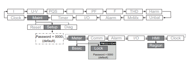
Configuration
Ethernet
Applicable only to PM5320, PM5340, and PM5341. To configure the IP address:
- Navigate to Maint > Setup > Comm > Enet.
- Configure the IP Address, Subnet Mask, and Gateway.
- Ensure the Modbus TCP protocol is enabled (usually Port 502).
RS485
NOTE: RS485 Device Addresses
- You MUST give each device on the RS485 bus a unique address. Check the manual of the device on how to do this.
- Use lower addresses first (1, 2, ...) because the SmartgridOne Controller will find them faster!
- For each device, it is generally recommended to stick with the factory default baud rate, parity, and stop bits. The SmartgridOne Controller will scan on those first.
To configure the Serial settings (Baud rate, Parity, ID):
- Navigate to Maint > Setup > Comm > Ser.
- Edit the Address (Unit ID), Baud rate, and Parity to match your gateway settings.