MasterPact MTZ
The MasterPact MTZ is a high-power air circuit breaker equipped with the MicroLogic X control unit. It provides advanced energy monitoring and protection.
Supported Devices
The driver supports the MasterPact MTZ range (MTZ1, MTZ2, MTZ3) when communicating via Modbus RTU.
| Device Type | Modbus TCP (Ethernet) | RS485 |
|---|---|---|
| MasterPact MTZ (MicroLogic X) | ❌ | ✅ |
This driver interacts with the MicroLogic X control unit. Ensure your breaker is powered and the control unit is active (The "Ready" LED should be blinking green).

Wiring
The MasterPact MTZ communicates using the internal ULP protocol. It does not have direct RS485 screw terminals on the breaker itself.
To connect it to the SmartgridOne Controller via RS485, you must use the EcoStruxure IFM Interface (Ref: LV434000).
Step 1: Connect the ULP Cord
- Locate the ULP Port on the MasterPact MTZ (usually located on the front or connection area of the chassis).
- Connect a ULP cord (RJ45) from the breaker to the bottom of the IFM Module.
Step 2: Connect RS485 to the IFM Module
- Snap the IFM Module (LV434000) onto the DIN rail.
- Wire the Top Connector (green 5-pin connector) to the SmartgridOne Controller RS485 bus.
- For correct RS485 wiring: Follow the guidelines for RS485 wiring.
- If the wiring shown in the table below is incorrect, please let us know.
- There is no general consensus in the industry about the usage of A and B for the RS485 polarity, so it may be counterintuitive and opposite of what you might expect for some devices.
| Device | SmartgridOne Controller model OM1 | SmartgridOne Controller model IG8 | RS485-USB converter | RS485-Ethernet converter |
|---|---|---|---|---|
| D1 (+) | RS485 A | RS485_POS | RS485 A | TX+ |
| D0 (-) | RS485 B | RS485_NEG | RS485 B | TX- |
| 0V / Common | RS GND | GND | Not available | G |
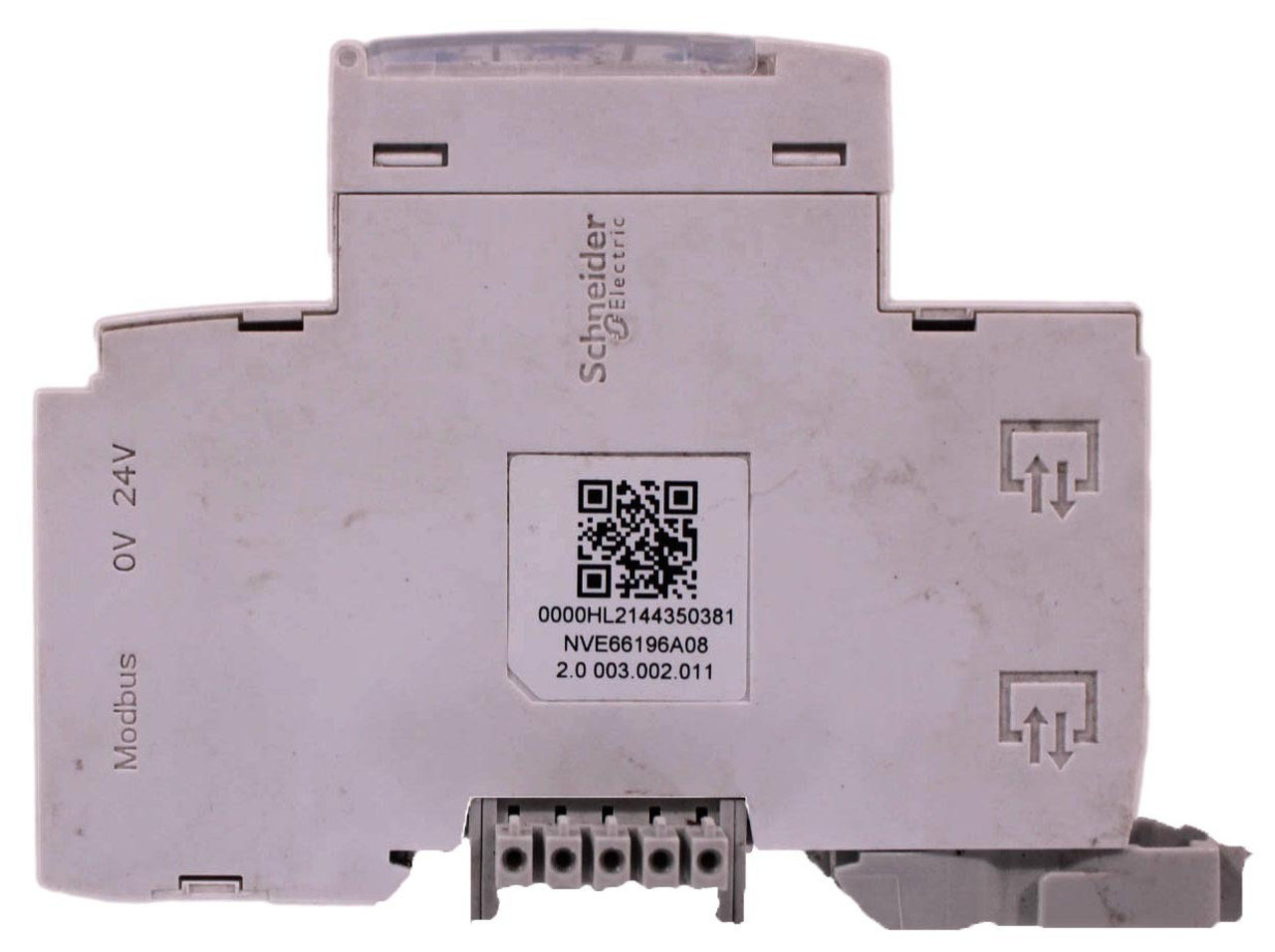
ifm module
Configuration
The configuration is handled physically on the IFM Module, not on the breaker's screen.
1. Set Modbus Address
Use the two rotary dials on the front of the IFM module to set the Modbus address (1 to 99).
- Tens Dial (x10): Sets the first digit.
- Ones Dial (x1): Sets the second digit.
- Lock: Slide the switch to the Padlock position to save the address.
- You MUST give each device on the RS485 bus a unique address. Check the manual of the device on how to do this.
- Use lower addresses first (1, 2, ...) because the SmartgridOne Controller will find them faster!
- For each device, it is generally recommended to stick with the factory default baud rate, parity, and stop bits. The SmartgridOne Controller will scan on those first.
2. Communication Settings
The IFM module automatically detects the baud rate and parity. However, ensure your SmartgridOne Controller and the IFM are aligned.
Recommended settings for the IFM:
- Baud Rate: 19200
- Parity: Even
- Stop Bits: 1
3. Validating the Connection
The driver performs a validation check upon connection. It verifies:
- Frequency: Must be within 50Hz or 60Hz ranges.
- Voltage: Must be within standard grid voltage ranges (e.g., 230V, 400V, 690V).
If the driver fails to load, check the voltage readings on the MicroLogic X display. If the breaker sees 0V (is not connected to a live busbar) and is not powered by an external 24V supply, the communication might fail or be rejected by the driver's validation logic.