DEYE
Dispositivi Supportati
| Device Type | Variants | Modbus TCP (Ethernet) | RS485 | Curtailment |
|---|---|---|---|---|
| SG04LP3-EU | SUN-5/6/8/10/12K | ❌ | ✅ | ❌ |
| SG01LP1-EU | SUN-12/14/16K |
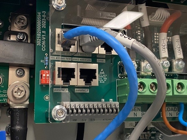
Cablaggio
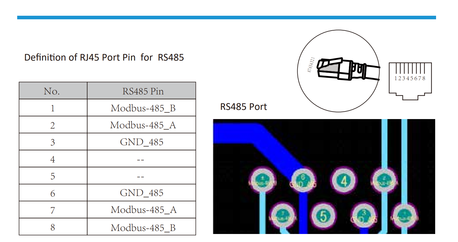
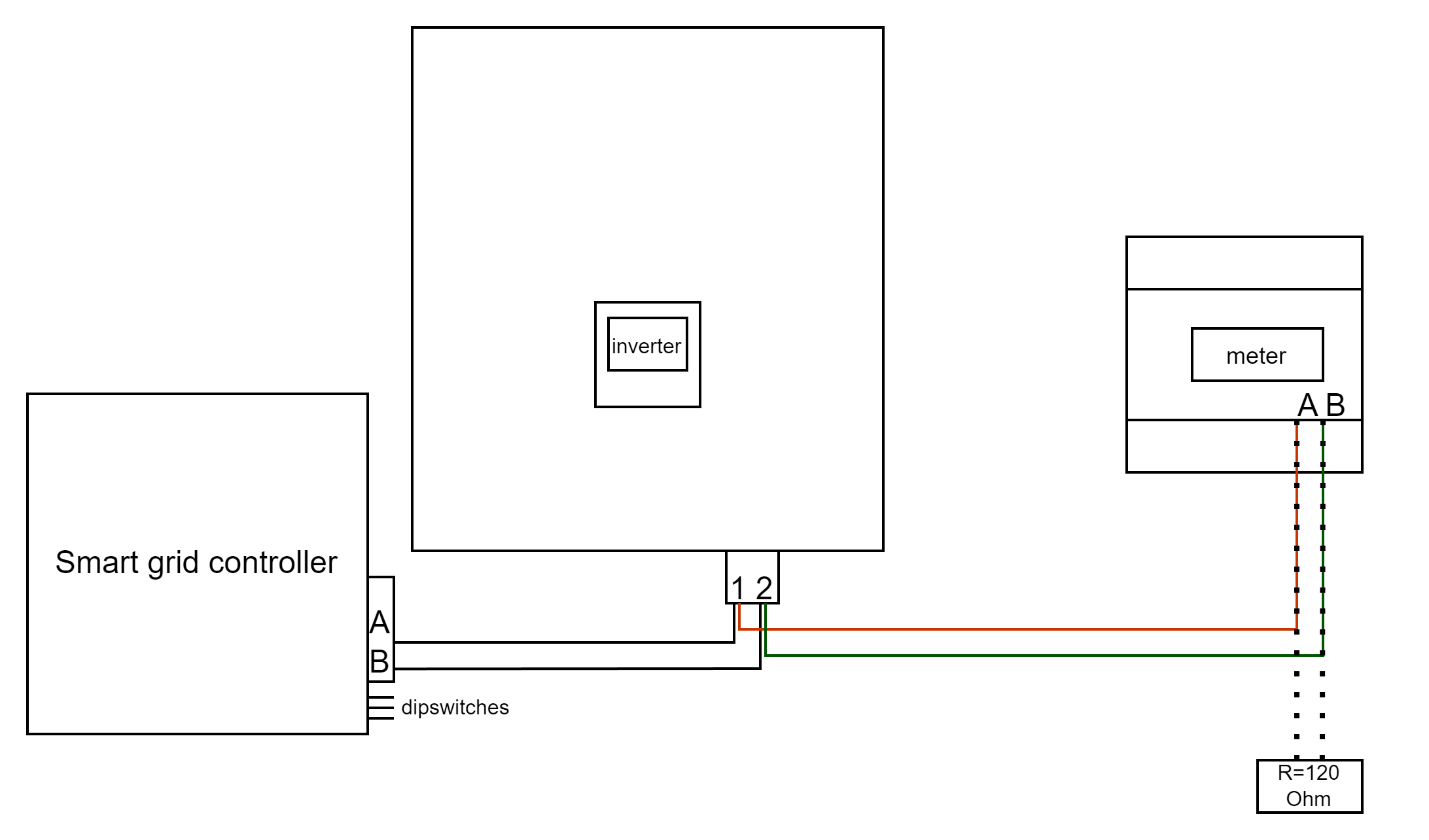
RS485
RS485 Wiring
- For correct RS485 wiring: Follow the guidelines for RS485 wiring.
- If the wiring shown in the table below is incorrect, please let us know.
- There is no general consensus in the industry about the usage of A and B for the RS485 polarity, so it may be counterintuitive and opposite of what you might expect for some devices.
| Device | SmartgridOne Controller model OM1 | SmartgridOne Controller model IG8 | RS485-USB converter | RS485-Ethernet converter |
|---|---|---|---|---|
| Pin 1 / Modbus-485_B | RS485 A | RS485_POS | RS485 A | TX+ |
| Pin 2 / Modbus-485_A | RS485 B | RS485_NEG | RS485 B | TX- |
| Pin 3 / GND_485 | RS GND | GND | Not available | G |
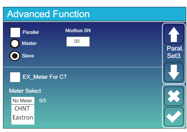
Configurazione
NOTE: RS485 Device Addresses
- You MUST give each device on the RS485 bus a unique address. Check the manual of the device on how to do this.
- Use lower addresses first (1, 2, ...) because the SmartgridOne Controller will find them faster!
- For each device, it is generally recommended to stick with the factory default baud rate, parity, and stop bits. The SmartgridOne Controller will scan on those first.
Vai a “Schermo Principale” >> “Impostazioni di Sistema” >> “Funzione Avanzata.”
- Il numero Modbus SN deve essere impostato su un numero tra 1 e 247. Non selezionare 0!! Nota che se ci sono più dispositivi sul bus RS485, ognuno deve avere un numero unico. Questo è l'indirizzo.
- Deve essere selezionato Slave.
- Solo quando un ulteriore contatore è connesso direttamente all'inverter, deve essere selezionato “EX_meter For CT”. Se c'è solo un contatore in parallelo con il SmartgridOne Controller deve essere deselezionato.
- Assicurati che le seguenti impostazioni siano tutte corrette: "Max A Charge", "Max A Discharge", "Grid Charge Ampere"